


In modern data centers, maintaining high performance and low latency is crucial, especially with the rise of AI and machine learning applications that demand significant computational power and efficient data transfer. One critical aspect of achieving these goals is effective flow control within the network, particularly in RoCEv2 (RDMA over Converged Ethernet) deployments. This article delves into the intricacies of flow control mechanisms, such as Priority-based Flow Control (PFC), and explores the challenges and solutions associated with their deployment in RoCEv2 networks. Understanding these concepts is essential for network engineers and data center operators striving to optimize network performance and ensure seamless data communication.
1. Traditional Flow Control Mechanisms
Flow control refers to the mechanism where the receiver notifies the sender to stop transmitting packets before packet loss occurs, preventing frame loss during network congestion. When a port receives a packet, it first buffers the received packet. If the packet processing is delayed, the buffer may fill up, leading to frame loss. To prevent frame loss, the concept of Pause frames is introduced. When the buffer reaches a full threshold, the receiving port sends an XOFF Pause frame to the sending port, notifying it to pause transmission for a specific period (the duration can be parsed from the Pause frame). The sender stops all transmission operations until it receives an XON control message from the receiver or a timeout occurs.
Traditional flow control mechanisms apply to the entire port without distinguishing between different traffic flows.
2. Priority-based Flow Control (PFC)
Priority-based Flow Control (PFC), defined by IEEE 802.1Qbb, is a flow control mechanism based on priority. In traditional flow control, when a link (port) experiences congestion, all traffic on that link is stopped. In contrast, PFC allows for the creation of eight virtual channels on an Ethernet link, each assigned a priority level, enabling individual virtual channels to be paused and resumed without affecting other channels' traffic.
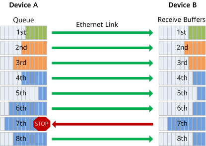
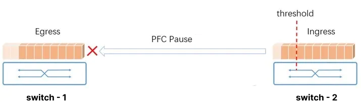
When a reception buffer on device B's interface becomes congested, device B sends a backpressure signal "STOP" to upstream device A. Device A, upon receiving the backpressure signal, stops transmitting packets for the corresponding priority queue and stores the data in its local interface buffer. Suppose device A's local interface buffer exceeds its threshold. In that case, it continues to propagate the backpressure upstream until reaching the network terminal device, thereby eliminating packet loss caused by congestion at network nodes.
Thus, PFC flow control targets one or several priority queues rather than interrupting all traffic on an interface. Each queue can individually pause or resume traffic transmission without impacting other queues, allowing for multiple types of traffic to share the link.
Priority queues can be mapped based on CoS or DSCP. Currently, most switch manufacturers and RoCE NICs support DSCP-based PFC.
3. Challenges in PFC Deployment
In actual PFC deployment, the following issues are commonly encountered:
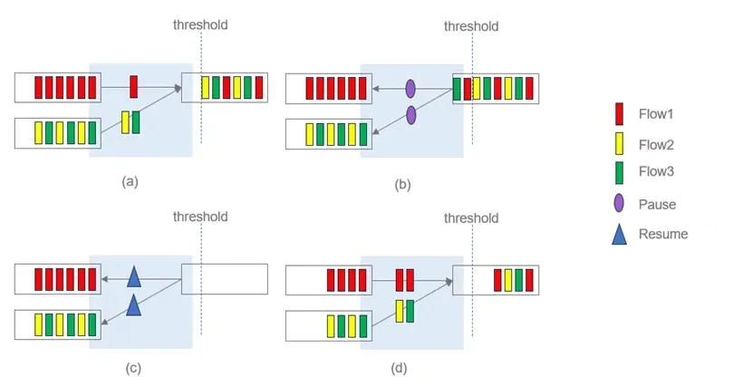
Unfairness Issue: In normal traffic scenarios (a), triggering a PFC Pause frame pauses two sending interfaces (b). When the receiving queue is free and sends a resume signal (c), both sending ports resume transmission simultaneously, causing Flow 2 and Flow 3 to compete for the same sending port. This results in Flow 1 consistently getting higher bandwidth compared to Flow 2 or Flow 3, leading to unfair bandwidth allocation across different flows.
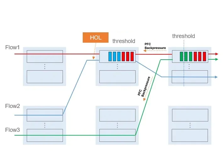
Head-of-Line (HOL) Blocking: As illustrated, Flow 1, Flow 2, and Flow 3 share the same priority and queue. Congestion caused by Flow 1 and Flow 3 affects Flow 2, even though Flow 2 does not experience congestion during forwarding. When the downstream port buffer reaches the PFC threshold, sending a backpressure signal to the upstream port stops all corresponding priority queues, causing HOL blocking for Flow 2.
PFC Storms: When devices do not drop packets upon buffer overflow but refuse additional packets, prolonged port queue blockage fills the target switch port queue, and Pause frames propagate upstream continuously. This results in endless PFC Pause frames along the traffic path to the source, known as a PFC storm.
PFC Deadlock: PFC deadlock occurs when congestion simultaneously affects multiple switches due to loops, causing port buffer consumption to exceed thresholds while waiting for each other to release resources, leading to permanent data flow blockage on all switches.
Detecting and preventing PFC deadlock is crucial. During deadlock detection periods, devices can resolve PFC deadlock by not responding to backpressure frames. However, this post-event unlocking only addresses low-probability PFC deadlock scenarios. Networks with multiple link failures causing loops may re-enter PFC deadlock immediately after recovery, significantly impacting network throughput.
4. PFC Deployment in RoCEv2 Networks
In lossless RoCEv2 networks, PFC flow control mechanisms prevent packet loss by pausing peer traffic before switch port buffer overflow. However, due to the need for tiered backpressure, efficiency is low, requiring more efficient end-to-end flow control capabilities.
The essence of PFC issues lies in the Pause mechanism operating at the port+priority level, unable to granularly manage each flow, crudely stopping the entire sending port. Dynamic adjustment of each flow's sending rate to maintain stable port queue depth can prevent PFC Pause triggers, necessitating flow-based congestion control algorithms.
Congestion control dynamically adjusts sending rates based on congestion severity, while PFC halts the sending port completely. Congestion control typically involves the receiver notifying the actual sender of congestion, carrying flow identifiers in congestion notification messages. The sender adjusts the flow's sending rate accordingly.
Common congestion control algorithms in RoCEv2 networks include ECN and DC-QCN (dependent on switch ECN marking). RoCEv2 networks achieve lossless guarantees through PFC and ECN deployment. ECN accurately marks congested traffic for precise rate reduction, achieving smooth rate reduction but responding slowly. Fast ECN, Fast CNP, and other auxiliary technologies are often needed for high microbursts and severe congestion to prevent packet loss before rate reduction. PFC responds quickly to alleviate congestion but can affect non-congested traffic and cause HOL blocking and PFC deadlock. PFC should be triggered sparingly, only as a last-resort safeguard. End-to-end congestion control methods should reduce traffic before PFC triggers, minimizing PFC activations.
PFC and ECN threshold settings must be tailored to specific scenarios. Adjusting ECN and PFC buffer thresholds so ECN triggers before PFC ensures continuous high-speed data forwarding, allowing servers to proactively reduce sending rates. If issues persist, PFC pauses upstream switch packet sending, reducing network throughput without causing packet loss. Threshold settings significantly impact performance; low ECN thresholds during mild congestion lead to excessive packet marking and over-throttling, degrading throughput. High thresholds during severe congestion delay rate reduction, causing packet loss or PFC triggers, and deep queues worsen latency.
In large-scale networks, PFC/ECN deployment faces numerous challenges. The industry continuously explores better flow control and congestion control solutions. Common congestion control algorithms include WRED/ECN-based CC, Credit-based CC, INT (in-band network telemetry)-based CC, and RTT (round-trip time, latency indicator)-based CC.
5. NADDOD's Recommendations
To effectively manage flow control in RoCEv2 networks and address the challenges associated with PFC deployment, NADDOD suggests the following strategies:
Comprehensive Testing: Conduct thorough testing of PFC and ECN settings in controlled environments to determine their impact on your network topology. This helps in identifying optimal threshold settings and mitigating potential issues before live deployment.
Advanced Congestion Control Algorithms: Utilize advanced congestion control algorithms such as WRED/ECN, Credit-based, INT-based, and RTT-based CC. These algorithms dynamically manage flow rates and prevent congestion from escalating to the point where PFC needs to be triggered.
Deploy High-Performance Transceivers: Use NADDOD’s high-speed optical transceivers, DACs, and AOCs specifically designed for RoCEv2 networks. NADDOD's products are rigorously tested for compatibility and performance, ensuring low-latency and high-reliability performance in demanding data center environments.
Continuous Monitoring and Adjustment: Implement continuous monitoring of network performance and adjust PFC and ECN settings as needed. Utilize network telemetry and analytics tools to gain insights into congestion patterns, allowing for proactive adjustments to maintain optimal flow control.
By adopting these strategies, data center operators can effectively manage flow control in RoCEv2 networks, minimizing packet loss and ensuring smooth, efficient data transmission. NADDOD’s comprehensive range of high-performance networking solutions provides the reliability and efficiency needed to support modern data-intensive applications.


 800GBASE-2xSR4 OSFP PAM4 850nm 50m MMF Module
- 1RoCE's Application in High-Performance Computing
- 2What is High-Performance Computing (HPC)?
- 3AI Boom Fuels Optical Transceiver Surge
- 4NVIDIA GB300 Deep Dive: Performance Breakthroughs vs GB200, Liquid Cooling Innovations, and Copper Interconnect Advancements.
- 5Blackwell Ultra - Powering the AI Reasoning Revolution