


1. Common Types of Optical Modules
1.1 Classified by Transmission Rate
To meet the demands of various transmission rates, different-rate optical modules have emerged: 400GE optical modules, 100GE optical modules, 40GE optical modules, 25GE optical modules, 10GE optical modules, GE optical modules, FE optical modules, and so on.
1.2 Classified by Package Type
As the transmission rate increases, the structure becomes more complex, resulting in different packaging methods. Commonly used packaging types for switches include: OSFP, QSFP-DD, QSFP56,QSFP28, QSFP+, SFP28, SFP, SFP+, CXP, CFP, and others.
|
Package Types |
Basic Explanation |
Appearance Diagram |
|
SFP Optical Module |
SFP (Small Form-factor Pluggable) Optical Module: Small pluggable SFP optical module supporting LC fiber connectors. |
|
|
SFP+ Optical Module |
SFP+ (Small Form-factor Pluggable Plus) Optical Module: Refers to SFP modules with increased data rates, making them more sensitive to electromagnetic interference (EMI). They have more skirt fingers on the shell and tighter fitting cages. |
|
|
SFP28 Optical Module |
SFP28 (Small Form-factor Pluggable 28) Optical Module: Interface package size identical to SFP+, supporting both 25G SFP28 and 10G SFP+ optical modules. |
|
|
QSFP+ Optical Module |
QSFP+ (Quad Small Form-factor Pluggable) Optical Module: Four-channel small pluggable hot-swappable optical module. QSFP+ optical modules support MPO fiber connectors and are larger in size compared to SFP+ optical modules. |
|
|
QSFP28 Optical Module |
QSFP28 (Quad Small Form-factor Pluggable 28) Optical Module: Interface package size identical to QSFP+, supporting both 100G QSFP28 and 40G QSFP+ optical modules. |
|
|
QSFP-DD Optical Module |
QSFP-DD (Quad Small Form-factor Pluggable-Double Density) Optical Module: Double-density four-channel small pluggable packaged optical module, defined by the QSFP-DD MSA group as a high-speed pluggable module. |
|
|
OSFP Optical Module |
OSFP (Optical Small Form Factor Pluggable) is a standardized interface for high-speed optical communication, designed for optical modules with speeds of 400G and above. It offers higher data throughput and improved heat dissipation to accommodate faster transmission rates. |
|


1.3 Classified by Mode
Optical fibers are classified into single-mode fibers and multi-mode fibers. To accommodate different types of optical fibers, single-mode optical modules and multi-mode optical modules have emerged.
The center wavelength of single-mode optical modules is generally 1310nm or 1550nm, compatible with single-mode fibers. Single-mode fibers have a wide transmission bandwidth and large capacity, suitable for long-distance transmission.
The center wavelength of multi-mode optical modules is generally 850nm, compatible with multi-mode fibers. Multi-mode fibers suffer from modal dispersion defects, resulting in poorer transmission performance compared to single-mode fibers. However, they are cost-effective and suitable for smaller capacity and short-distance transmission.
When using long-distance optical modules, the transmitted optical power is generally greater than the overload optical power, so it is necessary to pay attention to the fiber length to ensure that the actual received optical power is less than the overload optical power. If the fiber length is short, when using long-distance optical modules, it is necessary to use fiber attenuation (the attenuation value per unit length of fiber, measured in dB/km) to avoid burning out the optical modules at the other end.
1.4 Classified by Central Wavelength
The operational wavelength of optical modules is specified as a range, but for ease of description, the parameter of central wavelength, measured in nanometers (nm), is used.
To support the transmission of optical signals in different optical bands, optical modules with different central wavelengths have emerged, such as optical modules with central wavelengths of 850nm, 1310nm, and 1550nm.
1.5 Classified by Color
The key difference between color-coded optical modules and other types of optical modules lies in the central wavelength:
Generally, optical modules are classified into three categories based on central wavelength: 850nm, 1310nm, and 1550nm. These optical modules have relatively uniform central wavelengths, often referred to as "black-and-white light" or "gray light."
Color-coded optical modules carry light with several different central wavelengths, resulting in a spectrum of colors. These optical modules are referred to as "color light."
Color-coded optical modules are further divided into coarse wavelength division multiplexing (CWDM) and dense wavelength division multiplexing (DWDM) modules. In the same wavelength band, DWDM modules offer more options, leading to more efficient utilization of wavelength resources. Different central wavelengths of light can be transmitted without interference within the same optical fiber. Therefore, multiple streams of light with different central wavelengths from multiple color-coded optical modules can be combined into one stream for transmission using a passive combiner. At the remote end, a demultiplexer separates the light based on different central wavelengths, effectively saving fiber resources. Color-coded optical modules are mainly used in long-distance transmission lines.
1.6 Examples of Classification
Based on the above classifications, below are some examples of commonly classified optical modules:
|
Classification |
QSFP-40G-LR4 |
QSFP-100G-CWDM4 |
QSFP56-200G-SR4 |
QSFP-DD-400G-SR8 |
QSFP-800G-2xFR4H |
|
Speed |
40GE |
100GE |
200GE |
400GE |
800GE |
|
Package Type |
QSFP+ |
QSFP28 |
QSFP56 |
QSFP-DD |
QSFP |
|
Mode |
Singlemode |
Singlemode |
Multimode |
Multimode |
Singlemode |
|
Center Wavelength(nm) |
1271、1291、1311、1331 |
1271、1291、1311、1331 |
850 |
850 |
1300 |
2. Understand the Naming of Optical Modules
Understanding the naming rules of optical modules enables one to decipher all the information contained in the product names of manufacturers. This article breaks down and explains the information contained in the product names using universal naming rules.

|
Grade |
Meaning |
|
A |
Indicates the package type of the optical module, mainly:SFP+, SFP28 , QSFP+ , QSFP28 , QSFP56 , QSFP-DD , OSFP |
|
B |
Indicates the rate of the optical module, mainly:1GE, 10GE, 25GE, 40GE, 100GE, 200GE, 400GE, 800GE |
|
C |
Indicates the transmission distance type of the optical module: SX:Short Distance LX:Medium Distance LH:Long Distance |
|
D |
Indicates the transmission distance of the optical module in km. |
|
E |
Indicates the device class of the optical module, where:. SM: Single Mode MM: Multimode |
|
F |
Indicates the center wavelength of the optical module in nm. |
3. FAQ- The Main Causes of Optical Module Failure and Protective Measures
Optical modules must be operated in a standardized manner during application, as any non-standard actions may result in hidden damage or permanent failure.
3.1 Main Causes of Optical Module Failure
The primary causes of optical module failure are degraded performance due to electrostatic discharge (ESD) damage and optical link failure caused by contamination and damage to the optical interface. The reasons for optical interface contamination and damage include:
- Exposure of the optical interface of the optical module to the environment, leading to dust contamination.
- Contamination of the optical module's optical interface due to already contaminated fiber connector endfaces.
- Improper use of fiber optic connector endfaces with tails, such as scratching of the endface.
- Use of inferior quality fiber optic connectors.
Effective protection against optical module failure mainly involves ESD protection and physical protection.
3.2 ESD Protection
ESD damage is a major issue causing degraded performance or even loss of optoelectronic functionality. Additionally, optoelectronic devices damaged by ESD are difficult to test and screen, making it challenging to quickly identify failures.

Operating Instructions:
[1] Optical modules must be kept in anti-static packaging during transportation and handling before use and should not be removed or placed randomly.


[2] Before handling optical modules, anti-static gloves and wrist straps must be worn, and anti-static measures must be taken when installing optoelectronic devices (including optical modules).


[3] Testing equipment or application devices must have good grounding.

3.3 Physical Protection
The internal laser of the optical module and the temperature control circuit (TEC) are fragile and prone to fracture or detachment after impact. Therefore, physical protection should be observed during transportation and use.
Contaminants on the optical interface can be gently wiped off with a cleaning swab. Non-specialized cleaning swabs may cause damage to the optical interface, and excessive force when using cleaning swabs may result in metal scratches on the ceramic endface.
The design of the insertion and removal of optical modules is simulated for manual operation, and the pushing and pulling forces are also designed to simulate manual operation. Tools should not be used during installation and removal.
Operating Instructions:
[1] Handle optical modules with care during application to prevent dropping.
[2] When inserting the optical module, use hands to push it in and refrain from using other metal tools. When removing it, first open the pull ring to the unlock position before pulling it out; refrain from using other metal tools.

[3] Use specialized cleaning swabs for optical interface cleaning, and do not insert any other metal objects into the optical interface.
4. FAQ: What to Do When Optical Modules Cannot Communicate Between Switches
4.1 Background Information
In theory, interfaces of the same standard type can be connected, but attention should be paid to the optical power range and transmission distance during actual use. The main factors affecting the docking of optical modules are shown in the table below.
|
Factor |
Description |
|
Wavelength Mode |
Docking of optical modules of different wavelengths is prohibited. Due to the different transmission loss and dispersion in the optical fiber, the transmission distance corresponding to different wavelengths at the same rate is not the same, so it is necessary to choose the same wavelength optical module when docking. |
|
Transmission Distance |
Optical modules require peer-to-peer use, the interface indicators of different distance optical modules vary greatly, the price of long-distance optical modules is also high, so the long-distance optical modules and short-distance optical module docking, must be increased through the optical attenuator docking; in order to avoid not burned optical modules, it is recommended that the optical module to support the distance should not be less than the length of the optical fiber. |
|
Speed |
Optical module nominal rate and the actual link rate should be the same, low rate optical module is strictly prohibited to run high-speed signals. Optical module nominal rate must be greater than the interface rate. |
|
Mode |
Optical fiber and optical module should be used in pairs, that is, single-mode optical module using single-mode fiber, multi-mode optical module using multi-mode fiber, do not mix. |
4.2 Symptom
The optical interfaces of two switches are connected via fiber optic cables, but the local port is down, and the optical module cannot communicate.
4.3 Possible Causes
- The optical module used is not certified by Huawei for data center switches.
- Mismatch between the optical module and the fiber optic cable.
- The port is shut down.
- The transmit optical power is too low or too high.
- The receive optical power is too low or too high.
- Mismatched optical modules at both ends of the connection.
4.4 Troubleshooting Steps
[1] Confirm whether the optical module on the down port is certified by Huawei for data center switches. CE series switches require the use of optical modules certified by Huawei for data center switches. Non-certified optical modules may lead to unreliable port status.
[2] Check if the optical module and fiber optic cable are matched.
- Single-mode optical modules (usually with wavelengths of 1310nm, 1550nm) correspond to single-mode fiber optic cables (usually yellow).
- Multimode optical modules (usually with a wavelength of 850nm) correspond to multimode fiber optic cables (usually orange).
- Execute the command "display interface transceiver" to check whether there are any alarm messages under "Alarm information" for the optical module.
If an LOS (Loss of Signal) Alarm occurs, it indicates that no signal is being sent from the remote end. In interface mode, execute the command "display this" to check if both ends of the port are shut down. If the port is shut down, execute the "undo shutdown" operation.
- Execute the command "display interface transceiver verbose" to check the diagnostic information of the optical module. Check if there are any alarm messages regarding the transmission or reception optical power.
- In the diagnostic information of the optical module, you can view the current transmission and reception optical power values, as well as the default maximum and minimum power values.
- If the reception power is low (RxPower Low), it indicates that the signal received at this end is too weak. Check if the transmission distance exceeds the range supported by the optical module at the other end. Also, inspect if there is any damage to the optical module or fiber.
- If the reception power is high (RxPower High), it suggests that the signal received at this end is too strong. This may occur if the optical module at the other end is for long-distance transmission, while the actual distance is short. In this case, add an optical attenuator to the optical module at the other end to protect the optical module at this end.
- If the transmission power is low (TxPower Low), it indicates poor signal transmission from the optical module at this end or a fault in the optical module itself. Contact technical support for assistance.
- If the transmission power is high (TxPower High), it suggests that the signal transmitted from the optical module at this end is too strong, potentially damaging the optical module at the other end due to excessive reception power. This may be caused by a fault in the optical module at this end. Consider replacing the optical module.
After inserting the optical module into the port and successfully establishing a connection, investigate any alarm messages related to transmission or reception optical power to prevent abnormal traffic or module behavior due to excessively low or high power.
- If neither end has any alarms, and the port remains down, capture detailed information and logs of the optical module. Then, attempt to replace the fiber or optical module to see if the port comes up. If it does, it indicates a problem with the original fiber or optical module. Replace them with new ones. If the issue persists, contact technical support.
In the optical module industry, NADDOD offers high-performance 1G-800G optical modules, which have been validated by numerous internet companies. Colleagues are also planning to deploy them extensively in future data center upgrades. We welcome everyone to learn more and make purchases.

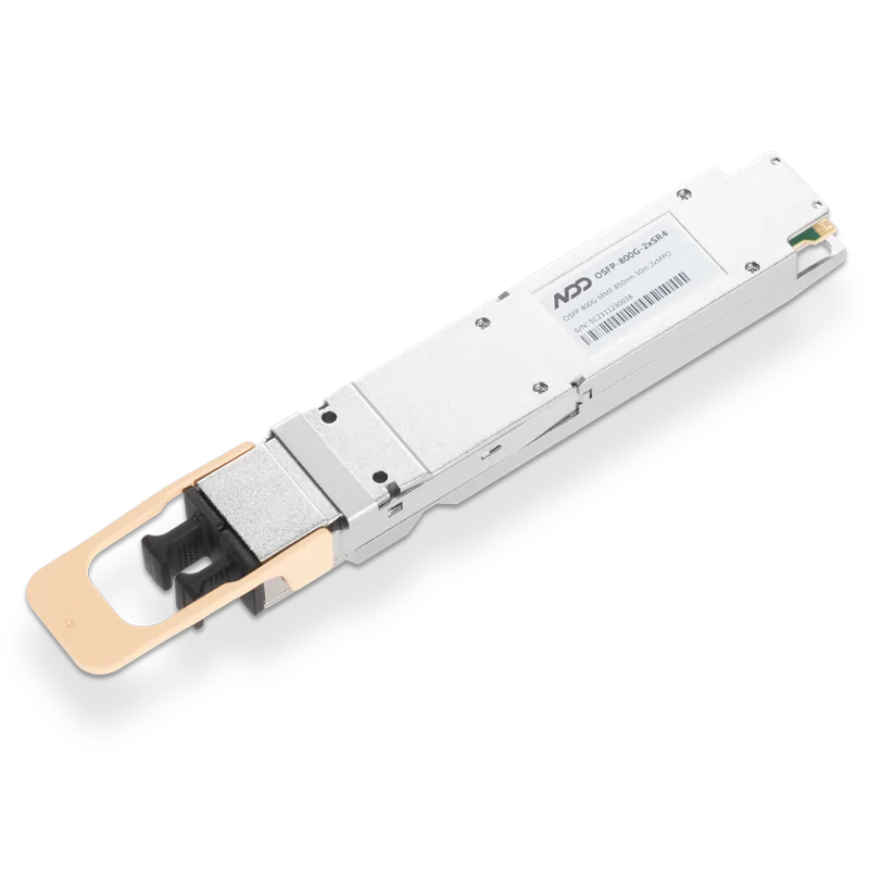 800GBASE-2xSR4 OSFP PAM4 850nm 50m MMF Module
- 1High Performance GPU Server Hardware Topology
- 2NVIDIA AI Landscape: NVLink, InfiniBand, and Ethernet Technologies
- 3What is Optical Module?
- 4Introduction to Open-source SONiC: A Cost-Efficient and Flexible Choice for Data Center Switching
- 5OFC 2025 Recap: Key Innovations Driving Optical Networking Forward


