


When it comes to the connection between two optical transceivers, how do you ensure interoperability between the two optical transceivers?

Condition 1: Same wavelength
In a fiber optic link, data is transmitted from one end to the other, and the optical transceiver is responsible for converting electrical signals to optical signals and vice versa. The optical transceiver should support the same wavelength at both ends for the conversion and transmission of the optical signals. The wavelengths of the optical transceivers need to be matched at each end, and wavelength mismatch may result in data loss during transmission. In addition, the operating modes of optical transceivers should be matched at both ends. Full-duplex optical transceivers should be paired with full-duplex optical transceivers; if full-duplex transceivers are connected with half-duplex (BIDI) transceivers, data transmission will not be possible.
Take NADDOD 10G SFP+ SR and 10G SFP+ LR optical transceivers for example, the transmission wavelength of SR is 850nm and the transmission wavelength of LR is 1310nm, so these two optical transceivers cannot be interconnected because of the inconsistent wavelength.
Condition 2: Same rate
In the use of optical transceivers, two similar-looking transceivers may be used in combination, or the same-sized optical transceivers may be inserted into the wrong switch port. In these cases, the optical transceiver is not working properly.
Example 1: Both ends of the switch have the different optical transceivers
The switch at end A is a 10G switch with NADDOD 10G SFP+ SR optical transceiver inserted; the switch at end B is a 25G switch with NADDOD 25G SFP28 SR optical transceiver inserted, in this case, the switch at end A and the switch at end B cannot be connected normally because the optical transceiver rates of the two switches are not the same.
Example 2: Both ends of the switch have the same optical transceiver
The 1G switch at end A and the 10G switch at end B are both inserted with NADDOD 10G SFP+ SR optical transceivers, in this case, end A will be limited to 1G while end B is 10G, in this case, the switch at end A and end B cannot be connected because the optical transceivers used at both ends are the same but the rates are not the same.
It follows that when the optical transceivers at both ends of the switch do not have the same rate, they cannot be connected.
Condition 3: The right fiber type
After the selection of an optical transceiver meets the above 2 conditions, the selection of the corresponding fiber type is also crucial. Usually, multimode optical transceivers need to be paired with multimode patch cords, and single-mode optical transceivers need to be paired with single-mode patch cords.
Condition 4: Proper operation of the switch
Before the optical transceiver is officially inserted into the switch, please make sure the purchased compatible transceiver has been tested on the original brand’s switch for normal communication to avoid abnormal operation.
All NADDOD optical transceivers will be tested in the targeted switch before shipment to ensure that the optical transceivers operate without errors
Optical Transceiver Interconnect FAQ
Q: Why doesn’t the port light come on when two optical transceivers are connected?
A:
- The parameters of the optical transceivers at both ends do not match, such as wavelength, rate, and transmission distance.
- The type of fiber optic patch cable used does not match with optical transceiver.
- The optical transceiver is not compatible with the switch brand.
Solution: First check whether the status of the optical port is on, then check whether the parameters of the optical transceiver at both ends match, whether the type of optical transceiver and the type of patch cord match and then check whether the configuration gateway and VLAN are consistent. If the switch brand is incompatible with the optical transceiver, you need to replace the compatible optical transceiver.
Q: Why does DDM receive low light after connection?
A: There are two general reasons for low DDM receiving light reception of optical transceiver:
- low luminescence of the peer transceiver;
- excessive loss due to problems in the link;
- damage to the optical transceiver detector.
Solution: When the DDM receiving light is low, first check whether the light emitted by the peer transceiver is normal; If the light is normal, then check whether the link is normal, available OTDR, end-face test instruments and another equipment testing; if there is no problem with the end transceiver and link, the optical transceiver detector may be damaged and need to be returned to the factory for maintenance.
Q: What if the switch indicator is red after the optical transceiver is inserted?
A: On the switch, different indicator lights have different meanings, the indicator lights we mentioned here refer to the Ethernet port status indicator. Generally, the green light means the port is connected, and the green light blinking means the port has data transmission. Besides the green light, the Ethernet port indicator light also has red and orange colors, for different brands or different models of the same brand of equipment, the meaning of the same color indicator light is also different. For example, some brands support multi-rate (1G/10G/25G or 100M/1G/10G) ports, so the link rate is differentiated according to the indicator color, while some brands use red or orange to indicate alarm information; when the switch Ethernet port indicator is red after the optical transceiver is inserted, first check the specific meaning of the indicator color of the device (usually available in the switch product manual), or log in to the switch product manual. If the transceiver inserted is not compatible, you need to replace the compatible transceiver.
Q: How to solve the alarm message of the interface after inserting the optical transceiver?
A: First of all, the type of alarm must be determined. If the alarm is not supported, unknown, unqualified, etc., it is because the transceiver is not compatible with the device, and compatible transceivers need to be replaced; If there is a light-receiving power warning, you need to check whether the transceiver failure or with the patch cord problem.

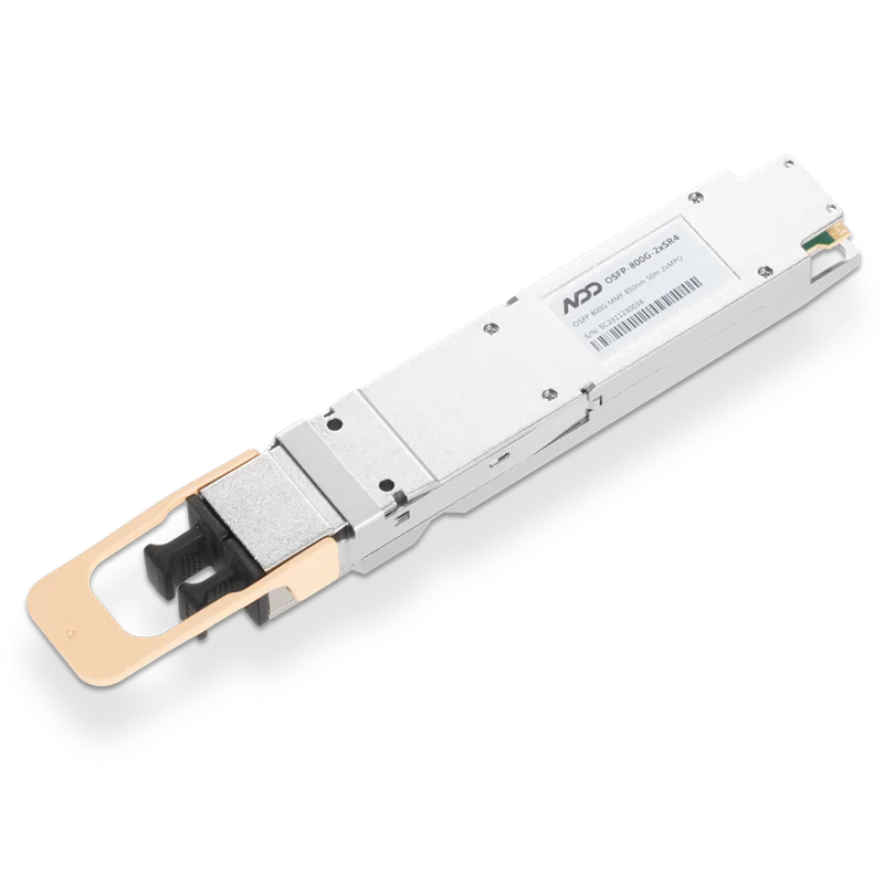 800GBASE-2xSR4 OSFP PAM4 850nm 50m MMF Module
- 1100G DSFP Network Card and 100G DSFP AOC Solution for Data Center
- 2What Is Passive Optical Network (PON)?
- 3Comparing Three 100G Multimode Transceivers for Data Centers: 100GBASE-SRBD, 100GBASE-SR4, 100GBASE-SWDM4
- 4NADDOD 1.6T XDR Infiniband Module: Proven Compatibility with NVIDIA Quantum-X800 Switch
- 5Vera Rubin Superchip - Transformative Force in Accelerated AI Compute