MTP/MPO systems are the solution to cable congestion problems in data centers or enterprise networks because of their flexibility, reliability and scalability. However, when faced with actual MTP/MPO networking systems, some network designers are faced with another challenge, which is to ensure the correct polarity of these array connections using end-to-end MTP/MPO multimode fiber components. The TIA 568 standard provides three methods to ensure that MTP/MPO systems operate at the correct polarity, and each of these methods is described in this article.
MTP/MPO Connector and MTP/MPO Polarity
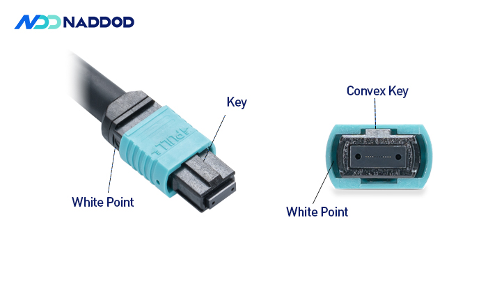
The MTP/MPO connector is a multi-innovative, high-performance fiber optic connector with enhanced optical and mechanical properties.
The special design of the MTP/MPO connector ensures the accuracy of polarity in MTP/MPO network systems.
But what is polarity? A typical optical link requires two fibers for the entire transmission process. For example, an optical module has a receiving end (Rx) and a sending end (TX). When in use, it is necessary to ensure that the receiving end and the sending end are in interconnection. This matching of the two ends of the optical link, the sending end and the receiving end, is called polarity. In common cabling systems, connectors such as LC and SC can be easily matched, so there is no polarity problem. However, for pre-terminated high-density MTP/MPO cabling systems, the polarity problem must be solved.
Three Cables with Three Polarization Methods
The three methods of ensuring correct polarity as defined by the TIA 568 standard are named Method A, Method B and Method C. To comply with these standards, three different configurations of MTP fiber, also known as Type A, Type B and Type C, are used for three different connection methods. This section will first introduce the three different fiber optic cables, and then the three connection methods.
MTP Backbone Cable Type A:
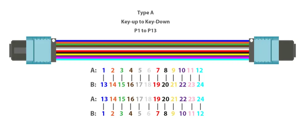
Type A cable is a straight-through fiber with a key-up MTP connector on one end and a key-down MTP connector on the other end. This allows the fiber to remain in the same position at both ends of the cable. For example, the fiber located at connector position 1 (P1) on one side will reach P1 on the other connector. 12 core MTP type A fiber optic patch cable has the fiber sequence as shown below.
MTP Backbone Cable Type B:
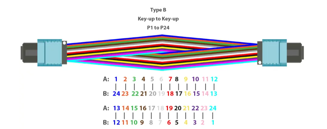
Type B cable (reversed cable) uses key-up connectors at both ends of the fiber optic cable. This type of array pairing causes the fibers to be inverted, which means that the fiber positions are reversed at each end. The fiber at P1 on one end is paired with the fiber at P12 on the other end. The diagram below shows the fiber sequence for a 12 core B-type fiber optic cable.
MTP Backbone Cable Type C:
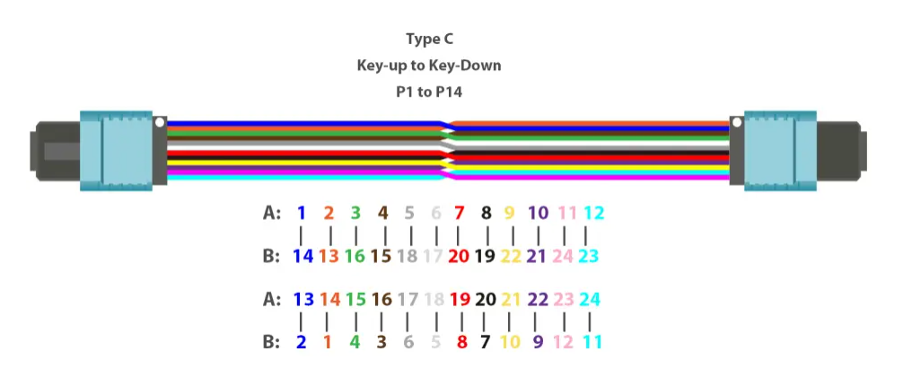
Type C cable (pairwise flip-flop cable) looks like Type A cable with one upward key connector and one downward key connector on each side. However, in Type C, each pair of adjacent fibers at one end is flipped at the other end. For example, the fiber in position 1 at one end is moved to position 2 at the other end of the cable. the fiber in position 2 at one end is moved to position 1 at the other end, etc. The fiber sequence for a Type C cable is shown in the figure below.
Three Connection Methods
Different polarization methods use different types of MTP backbone cables, but either method should use duplex patch cords for fiber optic link connections.The TIA standard also defines duplex fiber optic patch cords using LC / SC connectors: A-to-A patch cords - crossover version and A-to-B patch cords -pass-through version.

The following sections provide a description of how to use the components of the MTP system together to maintain the proper polarization connection, as defined by the TIA standard:
Method A
As shown in the figure below, Type A backbone cables connect the MTP modules on each side of the link. In Method A, two types of patch cords are used to correct the polarization. The jumper on the left is a standard duplex A-to-B type, while the jumper on the right is a duplex A-to-A type.

Method B
In connection method B, a Type B backbone cable is used to connect the two modules on each side of the link. As mentioned earlier, the fiber location of the Type B cable is reversed at each end, so a standard A to B duplex patch cable is used on both sides.

Method C
In connection Method C, pairs of reverse backbone cables are used in the connection, with one MTP module attached to each side of the link. The jumpers at each end are standard duplex A to B type.

24 Core MTP/MPO Polarity Solution
With the development of the Internet era, network upgrade to 40/100/400G has become an inevitable trend. To facilitate smooth network migration to 100G, 24 core MTP/MPO cables are generally recommended, however, maintaining the polarity of 24 core MTP/MPO cabling is complex. Currently, there is no industry standard to define the type of 24-core MTP/MPO cable. Flying Speed (FS) recommends using Type A (keyed to keyed) MTP/MPO backbone cables and our Type A and AF patch panels, eliminating the need for Type A to A patch cords. The connection method is shown below.

Maintain MTP/MPO Polarity Rules When Establishing Connections
IT personnel need to be very careful when changing patch cords in the field when fiber optic patch cords have different polarity schemes. Those who do not understand polarity or are in a hurry to get equipment up and running may use patch cords incorrectly, which can affect the transmission of optical signals.
MTP/MPO Cable and Patch Cord Connection Rules
There are three general types of array (multicore) optical cable assemblies where A-to-A patch cords and A-to-B patch cords are available. Please note that the locating pins on the MTP/MPO connectors are important to maintain proper polarity. Therefore, you need to ensure proper pin placement before using patch cords to connect MTP/MPO fiber.
Type A to B LC/SC duplex patch cords are standard crossover cables that map Tx ports to Rx ports and ensure correct polarity by flipping the A to B. MTP backbone cable Type B reverses the fiber position at each end (1 to 12 and 12 to 1) and the connector keys all face up. It is recommended to use this cable connection to maintain proper MTP/MPO polarity.
MTP/MPO Cable and Cassette Connection Rules
The choice of the MTP / MPO cassette also determines the choice of the MTP / MPO electrical cable. You should preferably select a fiber optic patch panel with the appropriate locating pins so that the MTP/MPO patch panel fits perfectly with the MTP/MPO connectors on both ends of the MTP/MPO fiber optic cable. In addition, the back of the adapter installed on the patch panel defines it as Method A or Method B to comply with TIA standards.
Conclusion
Network designers use MTP/MPO components to meet the growing demand for higher transmission speeds. One of the biggest issues during this time - polarity - can be solved by selecting the correct MTP cable, MTP connector, MTP patch panel and fiber patch cord, and three different polarization methods can be applied to different situations to meet the needs of different applications.

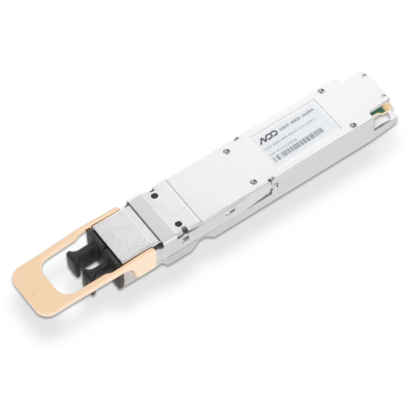 800GBASE-2xSR4 OSFP PAM4 850nm 50m MMF Module
- 1How to Check the Optical Transceiver Rate? How to Choose the Correct Rate?
- 2What is DDM for Optical Transceiver?
- 3Four Types of Typical 400G Network Solution Plan Explained
- 4Focusing AI Frontiers: NADDOD Unveils 1.6T InfiniBand XDR Silicon Photonics Transceiver
- 5NADDOD Leads in Compatibility and Performance on Thor2 & CX7


