


With the rapid rise of the Internet of Things, artificial intelligence, cloud computing, and big data applications, the data transfer rates of servers, routers, switches, and data storage devices are growing, and data centers are facing the challenges of high bandwidth, high reliability, and low latency, especially for data transfers of up to 800G.

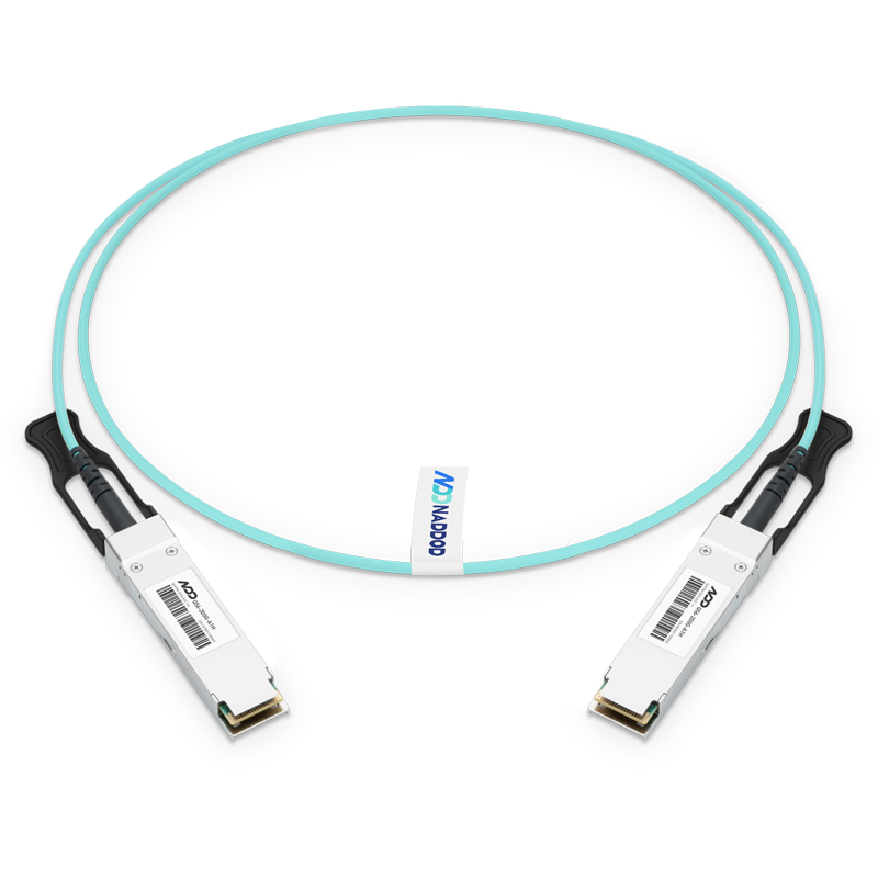
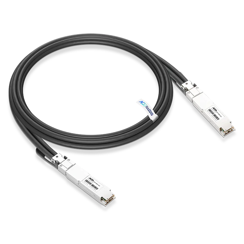
High data transmission requires cost-effective, stable and reliable data transmission cables and connectors. DAC high-speed cables with high simplicity and flexibility, as well as low power consumption, are cost-effective solutions for short-range, high-speed rate transmission in data centers.
800G QSFP-DD800 DAC data rate up to 800Gbps, using 8-way 112Gbps PAM4 modulation. A single 112Gbps high rate transmission means faster rising edges and higher bandwidth, which inevitably creates significant challenges for signal integrity. To meet the required insertion loss, return loss, TDR and crosstalk, high speed signal integrity simulation is inevitable.
High-speed signal integrity simulation requires a cable model and a QSFP-DD800 connector model. Since the vendor will not provide these two models, resulting in great difficulties in simulation, the following three main solutions are currently available.
DAC Signal Integrity Solutions
Solution 1
Simulation of only high-speed lines, signal vias and capacitors; cable soldering and QSFP-DD800 connectors (connected to gold fingers) are not simulated, but rely on empirical design.
Solution 2
Simulation of high-speed lines, signal vias, capacitors, cable pads and QSFP-DD800 connector pads, without building equivalent models for cables and QSFP-DD800 connectors, and directly adding excitation ports to cable pads and QSFP-DD800 connector pad locations for simulation.
Solution 3
Simulation of high-speed lines, signal vias, capacitors, cable soldering and QSFP-DD800 connectors, which requires the establishment of equivalent models for cables and QSFP-DD800 connectors.
Challenges to the Program
Challenge 1
The cable soldering and QSFP-DD800 connectors are the two locations with the most severe impedance mismatch, and relying on empirical design without signal integrity simulation will not allow real-world performance to be evaluated. The degree of impedance mismatch, the insertion loss/return loss values at high frequencies, and the presence of resonance are key information that cannot be obtained, leaving the entire design in a state of uncertainty, which is a huge risk that will not only make R&D more difficult, but also increase R&D costs and extend R&D cycles.
Challenge 2
Directly in the cable pad and QSFP-DD800 connector pad position plus excitation port for simulation, is a simple evaluation method, compared to the program will be improved, but the low impedance of the cable pad and QSFP-DD800 connector pad will distort the simulation results, and the simulation model is too different from the actual model resulting in the loss of very much detailed information (such as cable overhang, cable and pad soldering, QSFP-DD800 connector pin end overhang, QSFP-DD800 connector contact with pads resulting in parallel transmission of signals, etc., all these key information will have a great impact on the simulation results), which eventually leads to distortion of simulation results and affects the evaluation of signal integrity.
Challenge 3
Although signal integrity simulations for cable soldering and QSFP-DD800 connectors can help evaluate performance, the design quality of the equivalent model will determine the realism of the evaluated performance. Some equivalence models only consider realism, some equivalence models only consider equivalence, and the vast majority of equivalence models do not consider both realism and equivalence, which can lead to distorted simulation results and thus biased performance evaluation, and in severe cases, even wrong conclusions. How to strike a balance between realism and equivalence is a difficult and critical point in high-speed signal integrity simulation.
Technical Means to Overcome Challenges
Technical Means I: Establishing the Simulation Model of QSFP-DD800 Connector - Balancing Realism and Equivalence.
A signal integrity simulation method that balances the realism and equivalence of the QSFP-DD800 connector simulation model.
The processing method for restoring the realistic model of the QSFP-DD800 connector.
The design and simulation optimization method of the equivalent model of QSFP-DD800 connector.
Technical Means 2: building a simulation model of the cable - balancing realism and equivalence.
Signal integrity simulation methods that balance the realism and equivalence of the cable simulation model.
Methods of processing to restore the realistic model of the cable.
The design of the cable equivalent model and simulation optimization methods.
Technical means 3: cable pads out of the position for capacitive compensation - to avoid high-speed line impedance is pulled up to cause a serious impedance mismatch.
Design of rectangular copper skin for capacitive compensation.
Tolerance compensation to improve the signal integrity simulation method of 2 impedance discontinuity points (pad impedance point and outgoing differential pair impedance point) at the same time.

Figure 1: Insertion loss curve of QSFP-DD800 connector equivalent model.

Figure 2: TDR curve of QSFP-DD800 connector equivalent model.

Figure 3: The insertion loss curve of the cable equivalent model.

Figure 4: TDR curve of the cable equivalent model.

Figure 5: Comparison of rectangular copper skin capacitive compensation.

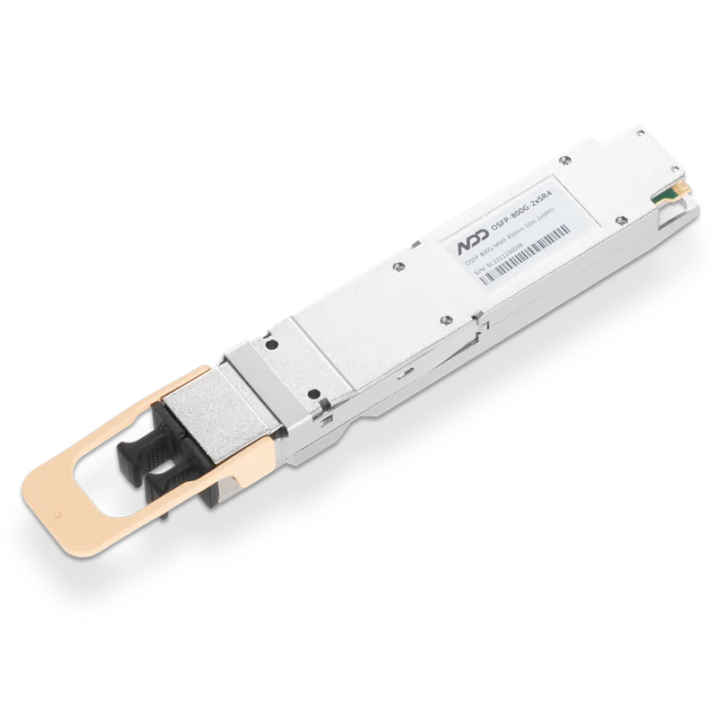 800GBASE-2xSR4 OSFP PAM4 850nm 50m MMF Module
- 1Exploring WDM-PON and Its Global Landscape
- 2Compare with PoE Switches, PoE+ Switches, and PoE++ Switches
- 3What Are Fiber Optic Cables and Pigtails?
- 4Introduction to Open-source SONiC: A Cost-Efficient and Flexible Choice for Data Center Switching
- 5OFC 2025 Recap: Key Innovations Driving Optical Networking Forward